The table shows the operating parameters required for hydraulic selection.
|
Up to three operating points can be defined for individual pumps. If several operating points are to be defined, the Operating data and Media data sections are given the corresponding number of columns. This makes it possible to define specific operating parameters for each individual operating point. Operating points are added using the button above the Design operating point combo box. The operating point, which is the reference point for the design of the pumps, is defined in the combo box. The design of the pumps in the selection is then based on the parameters defined for this point. |
The parameter list is available in a simple and an extended view. Both are divided into different areas to clarify the nature of the respective parameters.
|
In both variants, the mandatory values are marked with the symbol |
Simple view
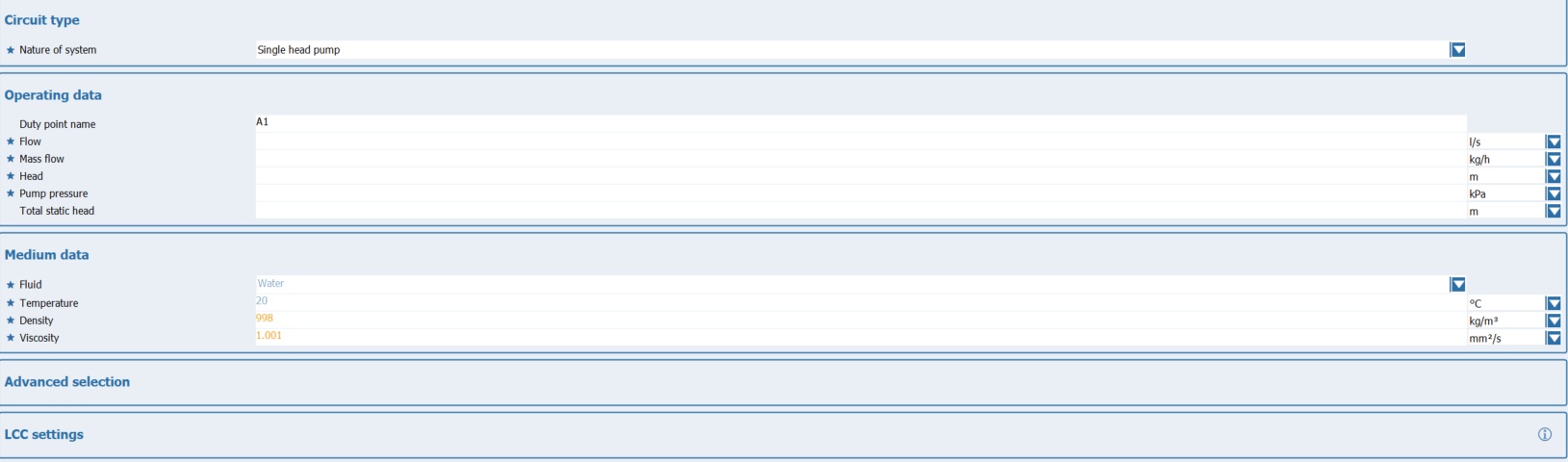
The simple view only contains the values that are absolutely necessary for the hydraulic selection.
Extended view
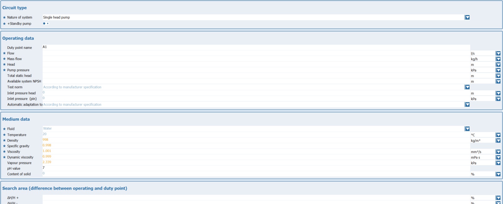
In addition to the necessary parameters, the extended view contains certain technical values and limit values that can be used to make the selection more precise.
The list of the extended view contains the following parameters:
Kind of circuit:
□Spaix ParallelPumping add-on module: Module is used to calculate pump characteristics when connecting the same or different pumps in parallel.
□Nature of System: The system type determines whether a single-pump or multi-pump system is to be used. Depending on the type of pumps, the following options may be available:
□ Single head pump
□ Several (single) pumps in series
□ Several (single) pumps in parallel
□ Several different pumps in parallel
□ Booster set
□ Twin pump main peak
□ Twin pump main standby
□Number of pumps: For multi-pump systems (series, parallel and pressure boosting), specify the number of pumps in the system here.
|
This parameter is only available for multi-pump systems. |
□Type of reserve pump: For multi-pump systems (series, parallel and pressure boosting), you can specify the type of backup pump here. You have the following options to choose from:
□ Standby pump (as failure redundancy)
□ Standby pump for peak load
|
This parameter is only available for multi-pump systems. |
Operating data:
□Designation of the operating point: This field contains the name of the operating point. It can be changed at any time by entering the new designation directly in the field. By default, the program uses the designation A1 for the first operating point. For each additional operating point, the number is increased by 1, i.e. A2, A3 etc.
□Flow rate / mass flow: Flow rate and mass flow are complementary, i.e. one value is calculated by specifying the other. If the Show calculated lines option has been activated in the upper area, both values are displayed. If the option is inactive, the complementary value is hidden after a value is entered.
□Head / Pump pressure: Delivery head and delivery pressure are complementary, i.e. one value is calculated by specifying the other. If the Show calculated lines option has been activated in the upper area, both values are displayed. If the option is inactive, the complementary value is hidden after a value is entered.
□Total static head: The total static height specifies the height difference between the inlet of the suction pipe and the pump inlet. This value can be set here.
□NPSH value of the system: This field is used to specify the value for NPSH that should apply to the entire system. This does not have to be the same as the NPSH value of the pump.
□Testnorm: During the product search, the system checks whether the desired test standard is available for the product. If this is the case, the characteristic curve is converted using the specified devaluation. If the desired test standard is not available for the product, the standard test standard of the product is used. The actual test standard to which the characteristic curve then refers is displayed below the diagram.
□SPAIX NfpaSizer add-on module: Extension for designing fire extinguishing systems in accordance with NFPA20.
□Additional module SPAIX TestnormConverter: Conversion of the pump characteristics to a different acceptance tolerance.
□ Inlet pressure head/ Inlet pressure: Pre-pressure height and pre-pressure are complementary, i.e. one value is calculated by specifying the other.
□ Inlet pressure (pin):
□Automatic adaptation to the duty point: This is where you specify whether and in what form a performance curve adaptation to the operating point you have specified should take place. Depending on the optimization options available for the respective pump series, you can use the switch ![]() to select the appropriate optimization.
to select the appropriate optimization.
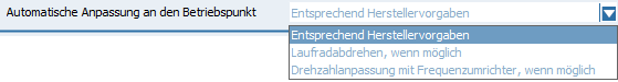
□ The option According to manufacturer's specifications is set by default. This performs an optimization as specified in the database program.
□ The impeller turning option, if possible, automatically performs a corresponding impeller optimization for the resulting selection, insofar as this is provided for the pump(s).
□ The option Speed adjustment with frequency inverter, if possible, first carries out a speed adjustment, if this is provided. The system then checks whether a frequency converter is assigned. If so, it is selected and the corresponding frequency converter curves are generated.
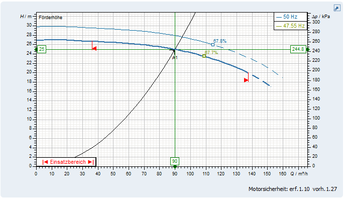
|
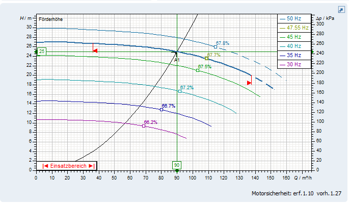
Example: Curve diagram with selected frequency inverter ( Increment = 0). |
|
|
|
Example: Curve diagram with selected frequency inverter ( Increment = 5Hz). |
|
|
Mediadaten:
The name of the medium is displayed in this field. A different medium can be selected using the button
|
The operating temperature for the medium is specified here. The temperature is the reference value for the following physical properties. If the corresponding data is available in the database, this value is used to automatically calculate the other physical properties of the medium. |
The density of the medium at the specified temperature is specified here. If the substance data is fully available for the medium, this value is determined automatically after the temperature has been specified.
|
The density ratio of the medium at the specified temperature is specified here. If the substance data is fully available for the medium, this value is determined automatically after the temperature is specified.
|
The viscosity of the medium at the specified temperature is specified here. If the substance data is fully available for the medium, this value is determined automatically after the temperature has been specified.
|
| Dynamic viscosity |
Enter the dynamic viscosity of the medium at the specified temperature here. If the substance data is fully available for the medium, this value is determined automatically once the temperature has been specified.
|
| Vapour pressure |
The vapor pressure of the medium at the specified temperature is specified here. If the substance data is fully available for the medium, this value is determined automatically after the temperature has been specified.
|
| pH value |
The vapor pressure of the medium at the specified temperature is specified here. If the substance data is fully available for the medium, this value is determined automatically after the temperature has been specified.
|
The solids content for the medium is defined here. This value is important with regard to the resistance of the components.
|
Search area
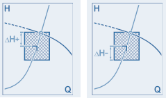
Use these two values to specify the maximum desired deviation of the actual operating point (intersection of the system curve with the performance curve) from the specified operating point in relation to the delivery head or delivery pressure as a percentage. Use ΔH + to specify the deviation upwards and ΔH - to specify the deviation downwards.
An explanatory graphic is displayed in the top right-hand corner of the dialog if the cursor is positioned in one of the two fields.
|
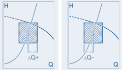
Use these two values to specify the maximum desired deviation of the actual operating point (intersection of the system curve with the performance curve) from the specified operating point in relation to the flow rate or mass flow in percent. Use ΔQ + to specify the deviation to the right and ΔQ - to specify the deviation to the left.
An explanatory graphic is displayed in the top right-hand corner of the dialog if the cursor is positioned in one of the two fields.
|
Advanced selection
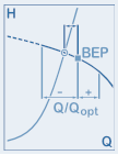
These two values specify the maximum desired deviation of the operating point (Q) relative to the design point (Qopt) in percent. Where Q/Qopt - is the deviation to the left and Q/Qopt + is the deviation to the right in the diagram.
An explanatory graphic is displayed in the upper right corner of the dialog when the cursor is positioned in one of the two fields.
|
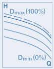
| Max. impeller trim |
The Maximum Trimming Diameter value determines the maximum percentage to which a wheel can be trimmed. The original diameter is assumed to be 100%.
|
||||
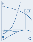
In this field, you specify the maximum percentage deviation of the efficiency of the determined actual operating point relative to the maximum efficiency of the corresponding characteristic curve.
An explanatory graphic is displayed in the upper right corner of the dialog when the cursor is positioned in this field.
|
This field specifies how the required power should be considered for motor selection. The following options are available:
□ According to manufacturer specification □ Engine power required for the operating point □ Maximum performance of the map □ Maximum engine power of the current characteristic curve
|
Ambient conditions:
| Attempts per hour: |
The number of starts per hour is a reference value for motor selection. During configuration, this value is compared to the maximum possible number of starts per hour for the motor. Motors with a lower value are excluded from the selection. |
The ambient temperature is a reference value for motor selection. This value influences the selection of motors based on their temperature classes.
|
| Installation altitude above sea level: |
|
LCC settings
| Operating costs settings: |
These options determine how operating costs should be calculated. The following options are available: □ Standard □ User defined □ Operation with constant flow according to DIN EN 17038 □ Operation with variable flow according to DIN EN 17038 □ DEA □ Default □ VB
|